

Click here to get the free Acrobat Reader software (Converted to pdf format thanks to Chris Lasley ).
The Micro-Guider III (MGIII) is a telescope to computer interface device based on my previous project, the Micro-Guider I. The original Micro-Guider I is a self-contained device which provides a telescope with digital setting circles, complete with a database of almost 8,000 celestial objects including the Messiers and the NGCs. It interacts with the user using an LCD display and a 16 button keypad. A detailed multi-part article entitled: "MICRO-GUIDER I: A Computerized Setting Circle/Database Device You Can Build" was published in Observatory Techniques #6 and #7 (Summer and Fall 1993).
The MGIII is a scaled-down version which reads the telescope's azimuth and altitude and transmits it to a suitable computer program upon request. This article will describe the MGIII's hardware, software, and construction. It is the author's intent to provide enough information here to allow the electronics-inclined telescope maker to build the device themselves. To aid in building the MGIII, the author has available a supply of blank printed circuit boards and the programmed EPROM chip needed to complete the device. Some other components may also be available.
The MGIII is a device which connects to a telescope by using two optical encoders, one attached to each axis of rotation. The optical encoders translate the rotational movements of the telescope into electrical signals which are interpreted by the MGIII's on-board microprocessor.
The current position of the telescope is transmitted to a computer upon request using a standard RS232 interface. The MGIII is used in conjunction with a suitable computer program which can translate the telescope's coordinates into right ascension and declination and act as an aid in locating objects at the eyepiece (preferably in a graphical way).
The MGIII is designed to be compatible with the author’s shareware Planetarium and Telescope Control Program for Microsoft Windows: The Earth Centered Universe (ECU). It is also compatible with other programs. ECU provides the interface between the telescope, the MGIII, and the user. I will not discuss the operation of ECU in this article, since the operating procedures are documented in ECU’s User's Manual.
As is normal practice with modern digital setting circles, the MGIII will work equally well with equatorial or alt-azimuth mounted telescopes, since it does not require polar alignment or mount levelling. Once aligned, ECU provides all the necessary mathematical conversions to use the elapsed time and the azimuth and altitude (from the MGIII) to calculate the current right ascension and declination. To initialize the system, ECU asks the user to point the telescope at two stars. Polar aligned equatorial telescopes need to be aligned on only one star.
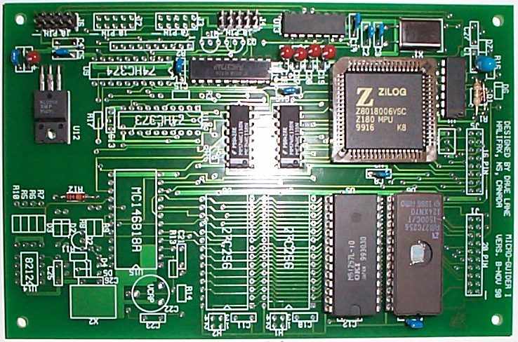
The MGIII's hardware consists of one printed circuit board; the same one used in the original Micro-Guider I except with fewer components installed. The schematic diagrams of the circuit board are depicted in Figure 1 (not included in the www version yet). The chassis wiring interconnecting the circuit board and the other components is shown in Figure 2 (not included in the www version yet). This section provides a brief description of how the MGIII works, however it is not required for the reader to understand how the hardware works to build the device.
The architecture of the MGIII is based on Hitachi's HD64180 microprocessor. This microprocessor is a highly integrated version of the older Zilog Z80 microprocessor. Components C2, C3, X1 comprise the main oscillator which is used to time all functions of the computer. U6 is the EPROM chip (32k bytes) which is used to store the MGIII's software. U5 provides 32K bytes of RAM for use by the software. Not all of this RAM is used; in fact an 8K byte device is sufficient.
The components mentioned in the previous paragraph form a complete fully operational computer. But a computer by itself, with no input/output, is all but useless. U11 is used to read the outputs from the encoders. Components U13, and C17-C20 are used to provide the RS232 interface. U12 is used to regulate positive five volts, which powers all of the circuitry. The minimum operating voltage is seven volts, but it will operate properly up to at least 15 volts. The current consumption of the complete MGIII is about 30mA, plus the current used by the encoders (the US Digital encoders consume about 17mA each). This will provide several hours operation from a standard 9V battery. I use a 12 volt 6 amp-hour gel-cell battery, which provides power for about a season of observing!
As mentioned above, the MGIII is basically a dedicated computer, thus the software reflects greatly in its functionality. The software was written in a combination of the 'C' programming language and assembly language. An important part of the software is the encoder routines, written in assembly language. The optical encoders are read by the software at a rate of 8000 times per second. Each optical encoder produces two signals which are used to determine the motion (including the direction) of each telescope shaft. The software interprets these signals to determine the azimuth and altitude of the telescope.
The remaining part of the program is the interface with the RS232 port. The port is configured at 9600 baud, eight data bits, and one stop bit. This portion is written in 'C'. There are several commands supported. The main command 'Q', queries the MGIII to transmit the current telescope position. It responds immediately by sending the azimuth and altitude out the RS232 port to the connected computer. The format transmitted is shown below:
+00123{tab}+00456{cr}
where:
The resolution of the encoders define the range of output expected in the azimuth and altitude readings. If 4000 count encoders are used, the range of output is -2000 to +1999 representing the angles -180 to +180 degrees. Several other commands can be sent to the MGIII for such functions as setting the encoder resolution, determining the number of encoder errors (if any), etc.
Determining the right ascension and declination of the telescope is quite complex and is calculated by the PC computer connected to the MGIII. The algorithm which The Earth Centered Universe uses is described in an article published in the Astronomical Computing column of the February 1989 Sky and Telescope magazine.
The construction of the MGIII is quite straight forward. The parts list shown below lists all the materials necessary to build the MGIII. Most are available from mail order outlets which cater to the hobbyist (consult the advertisements in a recent electronics hobbiest magazine). If materials sourcing proves difficult, the author is willing to assist the prospective builder. Many of the actual components listed in the parts list are only suggestions, and many substitutes are possible. The total cost of the parts is approximately $200US, including the two optical encoders.
The hardware for mounting the encoders to the telescope axis' will not be discussed here, since every telescope will require different mounting hardware.
Click here for an image of a completed MGIII pcb which may aid you during construction.
The circuit board should be populated according to the silkscreen markings on the PCB. Be careful to note the polarity of the diodes and capacitors and the orientation of the integrated circuits. Be particularily careful with U2 and its socket. Only install the components identified in the parts list. All of the other components are not required, since they are used only by the original Micro-Guider I, which has a real time clock, an LCD, and a keypad.
Components U2, and U6 should be socketed. The remaining IC's can be socketed, if desired. The chassis wiring can be performed using ribbon cable, as I have used, following the wiring diagram shown as Figure 2.
| RESISTORS | |
| R1 | 10K, 0.25W, 5% |
| R12,R16 | 100K, 0.25W, 5% |
| CAPACITORS | |
| C1,C6 | 10uF, 25V tantalum (0.2" lead spacing) |
| C5,C7,C8,C9,C12,C16 | 0.1uF, 50V, ceramic (0.2" lead spacing) |
| C2,C3 | 22pF, 50V, ceramic (0.2" lead spacing) |
| C17,C18,C19,C20 | 22uF, 16V, tantalum (0.2" lead spacing) |
| SEMI-CONDUCTORS | |
| X1 | 12.288MHz crystal (HC-18/U case style) |
| D1 | 1N4001 diode |
| U1 | 74HC14 IC |
| U2 | Zilog Z8018006VSC or Hitachi HD64180RCP-8X microprocessor |
| U3,U4 | 74HC138 decoder |
| U5 | Hitachi HM62256LP-12 (or equivalent) 32K static RAM |
| U6 | 27C256 EPROM Programmed |
| U11 | 74HC373 IC |
| U12 | 7805 IC (TO-220 case) |
| U13 | Maxim MAX232CPE IC |
| MISCELLANEOUS | |
| 1 | printed circuit board available from the author for $35US |
| 1 | 68 pin PLCC socket (for U2) |
| 1 | 28 pin IC socket (for U6) |
| 2 | 10 contact double row straight male headers for J4, J6 (0.1" pin spacing) |
| 1 | suitable enclosure |
| 2 | US Digital Corp. S1-1000 (0.09 degree resolution) optical encoders. Phone (800) 736-0194 or (360) 260-2468 |
| 2 | DB-9P connector |
| 2 | DB-9S connector |
| 2 | 10 pin IDC ribbon cable connector |
| 2 | encoder mountings (telescope specific) |
| RS232 cable to PC (straight through wiring DB-9S to DB-9P) | |
| Assorted wire and ribbon cable | |
| Assorted hardware |
(Note: A list of parts available from Nova Astronomics is here).
The MGIII provides an inexpensive and easy to build digital setting circle device. The author’s inexpensive shareware program for Microsoft Windows: The Earth Centered Universe (ECU) provides full support for the MGIII and many other telescopes. ECU, a full featured planetarium and telescope control program, is available from the author for $50US. The "shareware" version is available here.
David J. Lane, Nova Astronomics
PO Box 31013, Halifax, Nova Scotia, Canada, B3K 5T9
Phone: (902) 499-6196 evenings Fax: (902) 826-7957
E-mail: info@nova-astro.com
Go back to The Earth Centered Universe home page.
Last Updated: June 13, 2001 by David Lane, Nova Astronomics.